Catalog ID S03 · Stacking
Automatic Floor Deck Turnover Stacker
Servo-controlled receiving, mechanical turnover and stacking for long floor deck sheets. Review the actual sheet drawing and line sequence before selecting a configuration.
- Nominal cycle
- Approx. 25 s
- Listed length
- 6–12 m
- Servo axes
- 4
- Width entries
- 575 / 600 mm
Application
Mechanical turnover for long deck sheets.
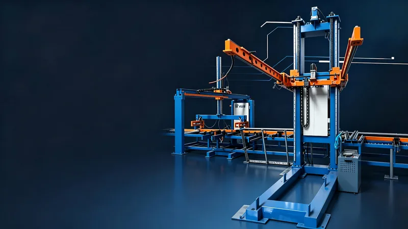
The presentation shows opposed turning arms, receiving rollers and lift/rotation/translation servo motions.
- Wecon VC1 PLC and touch screen
- Wecon lift, rotation and translation servos
- Sanmen Taili roller motor
- Wecon inverter and Impro RV reducer
Presentation specifications
Presentation-listed length: 6–12 m. The 575 / 600 mm entries do not identify overall width versus effective cover width. Approx. 25 s is a nominal cycle, not guaranteed line output. Confirm the drawing, incoming interval, turnover sequence and full-stack exchange conditions.
| Machine size | 2,100 × 2,300 × 4,500 mm |
|---|---|
| Moving-arm length | 1,500 mm |
| Roller conveyor | 10,000 mm long × 500 mm wide |
| Power supply | 220 / 380 V · 50 Hz |
| Air supply | 0.5–0.8 MPa |
| Environment | −20 to 40 °C; altitude below 2,000 m |
Mechanical turnover · selection scope
Start with the sheet, finish with the stack.
This equipment family uses mechanical turnover arms and receiving rollers—not a vacuum suction-cup handling system. Use the four views below to describe your project before requesting a configuration.
Conceptual input sketches only: not to scale, not a machine motion path, contact arrangement, operating recipe or compatibility approval.
- 01 · Profile & width
Two width references
Send the rib section, edge laps and gauge. Mark overall sheet width and effective cover width separately on the same drawing.
- 02 · Face identity
Incoming vs. finished face
Label a reference face on the drawing. Show which face arrives upward and which must be upward in the completed stack; also show travel direction.
- 03 · Mechanical interface
Review the actual geometry
Provide discharge height, sheet travel and the rib/edge geometry to review mechanical receiving and turnover. The illustration does not establish tooling or contact points.
- 04 · Full-stack handover
Name the next owner
Specify finished stack orientation, sheet quantity, supports and removal method. Confirm who takes over alignment, bundling and removal; none is assumed included.
Before configuration
Six questions worth settling first.
Is this a vacuum suction-cup stacker?
No. This page describes the mechanical floor-deck turnover equipment shown in the source presentation: opposed arms, receiving rollers and servo motions. Vacuum panel handling parameters are not transferred to this machine.
Do 575 / 600 mm mean overall and effective width?
That mapping is not confirmed by the existing product source. Keep both catalogue entries as supplied, and send a section drawing with separately labelled overall sheet and effective cover widths.
Does the approximate 25-second cycle guarantee line output?
No. It is the nominal value in the presentation, not a verified project throughput. Provide sheet length, line speed, arrival sequence, requested turnover and full-stack exchange conditions for review.
How should I identify the incoming and finished faces?
Label Face A and Face B on your actual section, show the incoming upward face and travel direction, then draw the requested completed stack. The examples here do not prescribe a layer pattern.
Are bundling and automatic stack removal included?
Do not assume they are. Describe the full-stack supports, quantity, orientation and removal method, and identify the next-process owner. Included scope and handover boundaries need project confirmation.
What should I send with a configuration enquiry?
Send your actual profile drawing, gauge, separately labelled widths, length range, line layout, face requirements and proposed full-stack handover. Use the input sheet and detailed support guide below to organise those materials.
S03 · English product brief
Download the floor-deck product brochure.
Three-page English PDF covering the presentation specifications, mechanical turnover, drawing inputs and full-stack handover. Width definitions, nominal-cycle conditions and unconfirmed lifting limits remain explicit. Updated 11 October 2026.
Download English PDF Product download center
The brochure is separate from the blank profile-stacking TXT input sheet below. It is not an operating manual or compatibility approval.
Project preparation
Bring the drawing into the enquiry.
Download the existing blank profile-stacking input sheet, then use the floor-deck guide for drawing references and handover questions. The TXT is a preparation form—not a capability approval, operating manual or product PDF.
Keep each reference explicit
- Profile drawing: ribs, edge laps, gauge and both width definitions
- Incoming face, travel direction and requested finished-stack face
- Line discharge layout and nominal-cycle conditions to review
- Full-stack quantity, supports, removal method and next-process owner
- Deck profile drawing, width and gauge
- Minimum and maximum sheet length
- Line speed and discharge height
- Stack quantity, orientation and removal method
Prepare your stacking project
Floor Deck Turnover Stacker: Selection Inputs · Compare purlin and floor deck requirements · Check existing-line integration · Download the project input sheet
Working with a different product? C/Z purlin stacker handles a different workpiece family: C- and Z-sections rather than deck sheets. Review its separate inputs; the link is not a compatibility or shared-specification approval.